Basic structure of pneumatic
actuator
Pneumatic actuators are actuators that use air pressure to drive open, close or adjust valves, also known as pneumatic
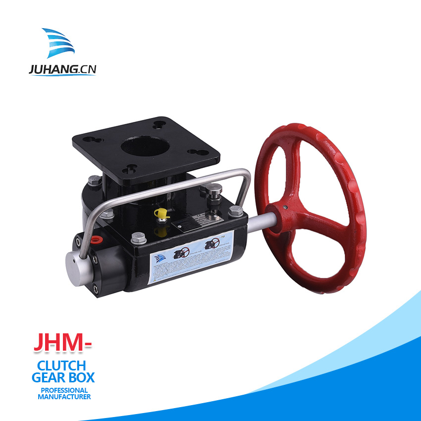
actuators or pneumatic devices, but they are generally called pneumatic heads. Pneumatic actuators are sometimes equipped with certain auxiliary devices. Commonly used are valve positioners and handwheel mechanisms. The function of the valve positioner is to use the feedback principle to improve the performance of the actuator, so that the actuator can achieve accurate positioning according to the control signal of the controller. The function of the handwheel mechanism is to use it to directly control the control valve to maintain normal production when the control system is powered off, gas out, the controller has no output or the actuator fails.
Basic structure of pneumatic actuator:
The type and structure of the adjustment mechanism of the pneumatic
actuator are roughly the same, but the main difference is the
actuator. Therefore, when the pneumatic actuator is introduced, it is divided into two parts: the actuator and the regulating valve. Pneumatic actuator consists of two parts: actuator and regulating valve (regulating mechanism). According to the size of the control signal, the corresponding thrust is generated to push the regulating valve to act. The regulating valve is the regulating part of the pneumatic actuator. Under the action of the thrust of the actuator, the regulating valve produces a certain displacement or rotation angle to directly regulate the flow of the fluid.
1. Pneumatic devices are mainly composed of cylinders, pistons, gear shafts, end caps, seals, screws, etc. The complete set of pneumatic devices should also include opening indication, travel limit, solenoid valve, positioner, pneumatic components, manual mechanism, signal Feedback and other components.
2. The connection size of the pneumatic device and the valve should meet the regulations.
3. The pneumatic device with manual mechanism should be able to use its manual mechanism to open and close the pneumatic ball valve when the air source is interrupted. When facing the handwheel, the handwheel or handle should be rotated counterclockwise to open the valve, and clockwise to open the valve. valve closed.
4. When the end of the piston rod has internal and external threads, there should be a wrench opening suitable for standard wrenches.
5. The sealing ring of the piston should be easy to replace and repair.
6. For the pneumatic device with buffer mechanism, the stroke length of the buffer mechanism can refer to the corresponding regulations.
7. For the pneumatic device with adjustable buffer mechanism, the buffer mechanism should be adjusted outside the cylinder body.
8. The thread size of the air inlet and outlet of the cylinder should meet the regulations.

